Approximate milling of circular grooves for shallow ceramic parts

Figure 1
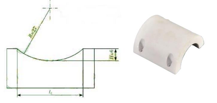
When machining ceramic parts with circular grooves of ceramic parts as shown in Figure 1, it is often encountered that the fixed tool size can not meet the circular radius size of ceramic parts designed for ceramic parts, and the processing efficiency of single-edge cutting tools is too low. According to the characteristics of such ceramic parts, the disk milling cutter (or end milling cutter) with the tool radius less than the arc radius of the ceramic part can be used at this time, and the vertical milling head of the vertical milling machine can be tilted at an Angle α to approximate the arc groove of the shallow ceramic part, and the accuracy requirements of the parts are not too high. The circular grooves of ceramic parts can meet the requirements of ceramic parts.

Calculation of arc dimension of ceramic parts
When machining circular grooves of shallow ceramic parts, the part to be cut out is a bow (see Figure 1). If the arc radius R and the bow height H of the ceramic part are known, the bow chord length L=2[H(2R-H)]½ : if the dimensions R and L are known, H=R-[R2-(L/2)2]½.
Approximate machining principle
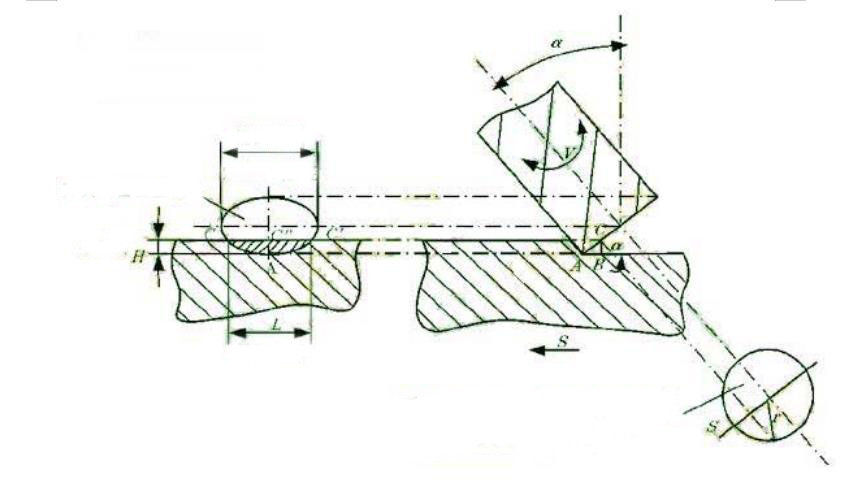
As shown in Figure 2, after rotating the end milling head (tool) at an Angle α, the projection of the tool end face perpendicular to the feed direction of the ceramic part is an ellipse, the long axis of the ellipse is A fixed tool diameter D, CC' is the bow chord length of the arc of the machining ceramic part, C"A is the bow height of the arc of the machining ceramic part, and C 'ac is the arc groove of the machined ceramic part. The shaded part in the figure is the actual cutting part of the tool. As can be seen from FIG. 2, C'AC is only the arc of a part of the elliptical ceramic part rather than the arc of a complete ceramic part, and the tool diameter D should be greater than the bow chord length L of the arc of the machining ceramic part. Therefore, this method of machining circular arc of ceramic parts with fixed value milling cutter is an approximate machining method.

Figure 2
Calculation of tool rotation Angle
By the figure 2 shows: D > = 2 L/H (2 r - H) 1/2 level, S = r - [r2 - (L / 2) 2] 1/2 level for the tool radius (r) by & Delter; ABC, the alpha is equal to the tool axis and the workbench of the vertical Angle, namely alpha = arcsin (H/S) = arcsin (H / {r - [r2 - (L / 2) 2] 1/2 level}). The formula is applied under the following conditions: R>r, L

Figure 3
Approximate degree analysis
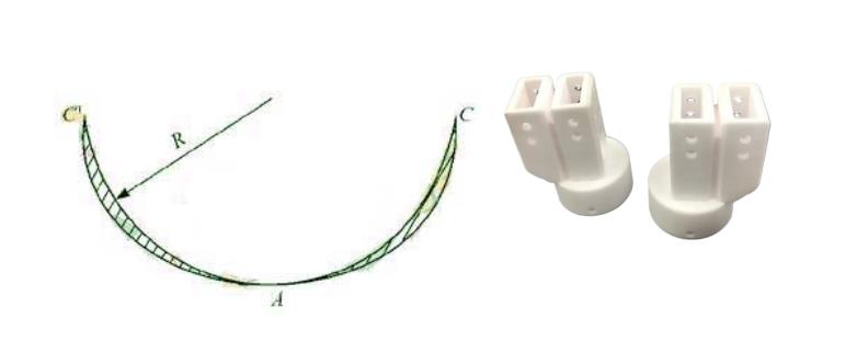
The projection of the real shape of the tool end face in the direction perpendicular to the ceramic part is an ellipse. As shown in Figure 3, the arc of the elliptic ceramic part coincides with the arc of the theoretical ceramic part at three points C, A and C' (that is, the coordinates are the same), and the arc of the elliptic ceramic part completely includes the arc of the theoretical ceramic part R, with only a small gap at AC' and AC arc. The closer the selected tool radius is to the circular arc radius of the ceramic part, the closer the circular arc of the machined elliptic ceramic part is to the circular arc of the ceramic part, and the smaller the matching gap with the matching part. For ceramic parts with low matching accuracy requirements, most of them can meet the requirements of use. However, this approximate machining method can not be used for the circular surface of ceramic parts requiring precision fit.
Processing Examples
To process the arc groove of the ceramic part shown in Figure 1, the steps are as follows :① Calculate the bow chord length of the arc groove of the ceramic part :L=2[H(2R-H)]½=2[6(2×27-6)]½=33.94mm. (2) calculation tool rotation Angle alpha: according to the ceramic parts ceramic parts arc radius R = 27 mm, primary Ø 50 vertical milling cutter, the alpha = arcsin (H / {R - / r2 - (L / 2) 2 1/2 level}) = arcsin (6 / {25-1/2 level} [252 - (33.94/2) 2]) = 6416 °, The result does not meet the requirement of α≤45°, and a tool with a smaller diameter should be selected: another Ø45 end mill is selected, and α=50.9°>45° is calculated, but it still does not meet the requirements: another Ø40 end mill is selected, and α=39.58°<45° is calculated, which meets the requirements. Therefore, the Ø40 end mill is selected as the approximate machining tool, and the rotation Angle of the tool is 39.58°. (3) Milling: Rotate the end milling head 39.58° and install the ceramic parts and tools according to the position shown in Figure 2 to milling.